The ASCA Technical Description provides proposers with information about ASCA and its scientific instruments (see also Tanaka, Inoue, & Holt 1994 Publ. Astron. Soc. Japan, 46, L37 for an overview). By reading this book and by using the associated software, proposers should be able to:
The second item is covered partly in Chapters 5, 6 & 7 which contain technical descriptions of the scientific instruments, the X-ray telescope (XRT), the Gas Imaging Spectrometer (GIS) and the Solid-state Imaging Spectrometer (SIS), respectively. The various operating modes of the GIS and SIS are described in their respective chapters.
Chapters 8 & 9 discuss the feasibility of carrying out a given observation with the GIS and SIS, respectively. These chapters deal with the various limitations of the two instruments.
Given the complexity of the ASCA instruments, care must be taken to demonstrate that a proposed observation is feasible. This is best done by creating and analyzing simulated data. Chapter 10 contains extensive documentation on how to do this using the programs XSPEC and PIMMS.
Although the GIS and SIS have broadly similar effective areas, pass bands and angular resolution, they do have significant and complementary differences. So, for a given investigation, the GIS could be more suitable than the SIS, and vice versa. But whichever instrument they choose to emphasize in their proposals, Guest Observers will always get data from the two GIS and two SIS instruments: during normal operation, the four focal plane instruments will always be collecting data. The detailed properties of the GIS and SIS are given in Chapters 6, 7, 8 & 9: here, to aid proposers, we give a quick comparison of the fundamental properties of the two instruments:
Investigators are strongly encouraged to keep abreast with the latest news and information by regularly consulting the ASCA GOF home page which has the URL:
http://heasarc.gsfc.nasa.gov/docs/asca/ascagof.html
In particular, the properties of the SIS are changing with time and this may affect the feasibility of a particular proposal.

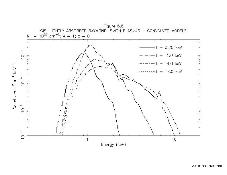
Figure 2.2a: Raymond-Smith models of various temperatures
(kT = 0.25, 1, 4, 16 keV) convolved with the combined response of
one XRT and one GIS. Each model has an absorbing column
of ![]() cm
cm![]() , solar abundance and zero redshift. All the
models are normalized to give
, solar abundance and zero redshift. All the
models are normalized to give ![]() erg cm
erg cm![]() s-1 in
the 0.5-12 keV band. Note that the instrument response
used is appropriate to the earliest observations performed
during the PV and AO-1 phases.
s-1 in
the 0.5-12 keV band. Note that the instrument response
used is appropriate to the earliest observations performed
during the PV and AO-1 phases.

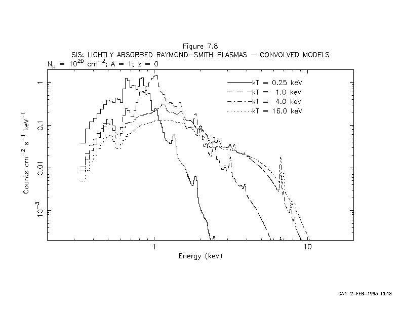
Figure 2.2b: Same as Figure 2.2a, but for one XRT and one SIS.