

Next: UV transmission
Up: Performance
Previous: Background
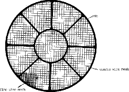
A schematic view of the window support structure is shown in
Figure 4.6  . The support structure consists of a rigid
circle (28 mm diameter) with 8 equally
spaced radial struts. Below this ``rib'' structure there are two mesh
systems, a coarse mesh of
  m tungsten wires with 2 mm
spacings and a fine mesh with
  m tungsten wires with 0.4 mm
spacings. The total (energy independent) transmission of this window
support structure is 79 percent apart from those areas of the detector
which are blocked by the struts. This average transmission
is obtained only over a sufficiently large area; over a smaller area the
actual transmission may increase or decrease depending on how much of
the area of the X-ray beam is occulted by the mesh grid wires.
In the vicinity of the center of the field
of view the focus of the X-ray beam from a point source is so sharp
and consequently the X-ray illuminated area on the PSPC so small
that significant shadowing can
occur behind the coarse mesh grid. Shadowing can also occur behind
the rib structure; however, the resolution of the telescope is already greatly
diminished at large off-axis angles (cf., Figure 4.4
  ).
Since the aspect control system
is quite stable, a slow spacecraft ``wobble'' will be performed.
A slow motion diagonally to the entrance window wire grids will be
carried out by the spacecraft (see § 3.4
  ).
In this fashion the coarse mesh grid will be smoothed
out when projected onto fixed sky coordinates and a permanent occultation
of X-ray sources behind the coarse wire mesh grid is not possible. In
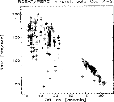
order to illustrate shadowing due to the window support structure,
Figure 4.7
  plots PSPC count rate versus off-axis angle for a
bright X-ray source,
Cygnus X-2. At off-axis angles larger than 40', the shadowing
due to the wires is completely negligible and loss of photons is dominated
by the mirror vignetting function.


Next: UV transmission
Up: Performance
Previous: Background
Michael Arida
Tue Jun 11 16:18:41 EDT 1996
 . The support structure consists of a rigid
circle (28 mm diameter) with 8 equally
spaced radial struts. Below this ``rib'' structure there are two mesh
systems, a coarse mesh of
  ).
Since the aspect control system
is quite stable, a slow spacecraft ``wobble'' will be performed.
A slow motion diagonally to the entrance window wire grids will be
carried out by the spacecraft (see § 3.4
  ).
In this fashion the coarse mesh grid will be smoothed
out when projected onto fixed sky coordinates and a permanent occultation
of X-ray sources behind the coarse wire mesh grid is not possible. In
order to illustrate shadowing due to the window support structure,
Figure 4.7
  plots PSPC count rate versus off-axis angle for a
bright X-ray source,
Cygnus X-2. At off-axis angles larger than 40', the shadowing
due to the wires is completely negligible and loss of photons is dominated
by the mirror vignetting function.


