Fabrizio Fiore![]() , Matteo Guainazzi
, Matteo Guainazzi![]() , Paola Grandi
, Paola Grandi![]()
![]() BeppoSAX Science Data Center, via Corcolle 19, I00131 Roma, Italy
BeppoSAX Science Data Center, via Corcolle 19, I00131 Roma, Italy
![]() Osservatorio Astronomico di Roma, Monteporzio, Italy
Osservatorio Astronomico di Roma, Monteporzio, Italy
![]() Astrophysics Division, SSD of ESA, Noordwijk, The Netherlands
Astrophysics Division, SSD of ESA, Noordwijk, The Netherlands
![]() IAS/CNR, Roma, Italy
IAS/CNR, Roma, Italy
version 1.2: 7 January 1999
This note integrates and expands the BeppoSAX SDC data analysis Cookbook
(http://www.sdc.asi.it/software/cookbook)
for what concerns the spectral analysis of Narrow Field Instrument and the combination of their data. We first briefly review the data reduction process and the products extraction processes, addressing issues important for a correct spectral analysis (Sect. 2 and 3). We then discuss in detail the problem of the NFI flux intercalibration (Sect 4.). We finally discuss briefly background subtraction issues for the LECS and MECS (Sect. 5). Detailed information on the four BeppoSAX NFI instruments can be found in Parmar et al. 1997, Boella et al. 1997, Manzo et al. 1997, Frontera et al. 1997, Conti et al. 1997.
Lucio Chiappetti has prepared ``A guided tour to the MECS and to its response matrix''
http://sax.ifctr.mi.cnr.it/Sax/Mecs
which illustrate MECS hardware and calibration issues.
BeppoSAX NFI data analysis can be performed starting from different products at different levels of complexity. The observer can:
The second (or even the third) strategy is adequate for most applications (unless the observer wants to access to the data excluded by the standard screening, or produce files with a revision different from that of the SDC archive files).
The SAXDAS software accesses the BeppoSAX FOTS and produces cleaned and linearized event files, very similar to ROSAT or ASCA event files (see http://www.sdc.asi.it/software for details).
LECS and MECS pipelines were available in the first SAXDAS issue on January 1997. They are described extensively on the SDC WEB pages.
PDS and HPGSPC pipelines are available in SAXDAS 2.0. At the moment they are not well documented so we give in the following a brief description of their use.
PDS and HPGSPC pipelines are run with the usual command:
saxpipe instr=PD
or
saxpipe instr=HP
For the PDS this will create one set of files called
fot_00${fotnumber}_PD_01_hkp.fits
(concatenated housekeeping file) and
fot_00${fotnumber}_PD_01_qev.fits
(concatenated gain equalized event file), unless there were changes in
the instrument configuration during the observation (this condition
can be recognized because the characters 01 in the above file
names are increased by integer units). A set of GTI files are created as
well. The GTI file
fot_00${fotnumber}_PD_01_gti00.fits
excludes the Earth occultation and passages through the
South Atlantic Anomaly.
the Earth occultation angle is chosen by default higher than
10 degrees to minimize the chances that the off-collimators point
too close to the Earth atmosphere, which can reflect
X and ![]() rays.
The first 5 minutes after the instrument
switch on after the passage are also usually excluded from the
analysis to allow the on board Automatic Gain Control to stabilize the
gain and to disregard periods of high and variable background. This
interval of time can be changed by the observer using the program
mkgti to create a new gti00 file.
rays.
The first 5 minutes after the instrument
switch on after the passage are also usually excluded from the
analysis to allow the on board Automatic Gain Control to stabilize the
gain and to disregard periods of high and variable background. This
interval of time can be changed by the observer using the program
mkgti to create a new gti00 file.
For the HPGSPC the pipeline will create a pair of files called
fot_00${fotnumber}_HP_01_hkp.fits
(concatenated housekeeping file) and
fot_00${fotnumber}_HP_01_evc.fits (gain equalized event file),
unless there were changes in the instrument
configuration during the observation.
A set of GTI files are created as well, selecting time
intervals for which the on board Automatic Gain Control is stable
(fot_005166_HP_01_gti_agc.fits), when the source is
not occulted by the Earth (fot_005166_HP_01_gti_occ.fits), and
when the source is more than 5 degrees distant from the bright
Earth's limb (fot_005166_HP_01_gti_vis.fits).
The data of the three (or two, after May 7 1997) MECS units (as well
as those of the four PDS units) are usually merged together to
increase the signal to noise ratio. This is feasible because a) the
three MECS units show very similar performance, b) the difference
in the position of the optical axis in detector coordinates in the
three units (1-2 arcmin) is smaller than the scale on which the
vignetting of the telescopes varies significantly (![]() arcmin).
Before merging the three MECS units event files, events are equalized
in energy to the Energy-PI scale of MECS1. This is done by the SAXDAS
meevelin program. MECS (three MECS units merged file) or MECS23 (two
MECS units merged file) event files produced by SDC and available in
the SDC archive, contain events already equalized. These data files
are also already screened for data in interval of time in which data
of one units are missing, due to telemetry losses. This is an
important point. Not excluding these time interval from the event
files would produce an artificially lower MECS or MECS23 count rate.
The exclusion is automatically done in the SDC pipelines through the
generation and the application of a dedicated ``gti'' file
(MECS_gti.fits or MECS23_gti.fits). The observer who has
retrieved the MECS or MECS23 files from the SDC archive
does not have to apply this file to his/her data.
arcmin).
Before merging the three MECS units event files, events are equalized
in energy to the Energy-PI scale of MECS1. This is done by the SAXDAS
meevelin program. MECS (three MECS units merged file) or MECS23 (two
MECS units merged file) event files produced by SDC and available in
the SDC archive, contain events already equalized. These data files
are also already screened for data in interval of time in which data
of one units are missing, due to telemetry losses. This is an
important point. Not excluding these time interval from the event
files would produce an artificially lower MECS or MECS23 count rate.
The exclusion is automatically done in the SDC pipelines through the
generation and the application of a dedicated ``gti'' file
(MECS_gti.fits or MECS23_gti.fits). The observer who has
retrieved the MECS or MECS23 files from the SDC archive
does not have to apply this file to his/her data.
If the observer has generated his/her own event files files running SAXDAS and wants to combine MECS units, then he/she has to:
sax-user > meevelin equalize=yes
mgtime "MECS1\_ObsCode.evt+3,MECS2\_ObsCode.evt+3,MECS3\_ObsCode.evt+3"
MECS\_gti.fits AND
mecs_merging:ASCA > read events
> Enter the Event file dir >[./]
> Enter Event file list >[] MECS1.evt MECS2.evt MECS3.evt

mecs_merging:MECS > filter time file MECS_gti.fits

mecs_merging:MECS > extract events

extract events:MECS > save events MECS.evt
The optical axis of the three MECS units does not intercept the focal plane in exactly the same point (i.e. the detector coordinates of the optical axis are not the same for the three MECS units). The difference between the position of the optical axis in the different units is of 1-2 arcmin. The OPTIC keywords of the merged MECS and MECS23 event files available from the on-line SDC archive contain an average of the OPTIC keyword values of the single units.
SDC maintains an on-line archive of SAX NFI files accessible through the network. Access to public data is free, proprietary data are protected by a password. The NFI data in the on-line archive are stored on magnetic disks for a faster access in a directory tree of the following type:
http://www.sdc.asi.it/archive/${obscode}              home directory
                                        /html         results from the S3A
                                        /event_files  event files, gti files
                                        /hk_files     housekeeping files
                                        /results      logs, spectra, light curves

(S3A = Standard Supervised Science Analysis)
LECS and MECS cleaned and linearized event (*.evt) files are available
from the on-line BeppoSAX SDC archive under the
archive/${obscode}/event_files directory. This directory
also contains *gti.fits, good time intervals (GTI hereinafter)
relevant to the LECS, MECS and PDS data analysis, see below. Raw LECS
and MECS event files along with raw and cleaned and linearized PDS
event files are not available directly on line because of their size
(typically 50-100 Mbyte each) and the reduced bandwidth of the SDC
internet connection. Starting from December 1 1997
these files are stored on CDroms in a juke-box at
SDC and are available on request.
LECS and MECS housekeeping and ratemeters file (*hkg* and *eng* files)
are available from the on-line BeppoSAX SDC archive under the
archive/${obscode}/hk_files directory. Gzipped
postscript files with plots of the
most interesting LECS and MECS housekeeping and ratemeters, along with
attitude and auxiliary ephemeris quantities, are also stored in this
directory. The same list of files,
together with PDS housekeeping files, is stored on CDroms.
PI Spectra, sky images and light curves can be easily extracted from
the event files using Xselect or dedicated software. Some of
these products (*.pha, *.lc files generated by the
SDC Supervised Standard Science Analysis) for the LECS, MECS and PDS are
available from the on-line BeppoSAX SDC archive under the
archive/${obscode}/results directory.
SAXDAS 2.0 released on December 1998 supports HPGSPC data reduction.
HPGSPC data files will enter the SDC archives starting from January
1999. HPGSPC event and housekeeping files will be available on
CDroms, HPGSPC background subtracted spectra and light curves will be
available on line under the archive/${obscode}/results
directory
SAXDAS software evolved quickly during the first year of the mission but remained rather stable after September 1997. The following are the major revisions up to December 1998:
revision           Dates           Main modifications with respect
                                   to the previous revision
--------------------------------------------------------------------
rev 0.0  1-Jan-1997  - 13-Feb-1997
rev 0.1  13-Feb-1997 - 25-Feb-1997 LECS foting, MEcalcgain
rev 0.2  25-Feb-1997 - 15-Aug-1997 MECS plate scale; PDS reduction
rev 1.0  15-Aug-1997 - 03-Sep-1997 update PDS and MECS equalization;
                                   corrected a bug in PDS bkg subtraction
rev 1.1  03-Sep-1997 - 30-Nov-1998 update MECS sky coordinate
rev 2.0  30-Nov-1998 -             update LECS BLselection; HPGSPC reduction
MECS and LECS files generated after 25-Feb-1997 can be safely used
(revision ![]() rev 0.2).
rev 0.2).
PDS files generated after 15-Aug-1997 can be safely used
(revision ![]() rev 1.0).
rev 1.0).
Please check the DATE keyword of the fits files extracted from the archive before using them.
Reprocessing of all data with revision 0.0 and 0.1 is in progress. SDC will then start reprocessing of data with rev 0.2 files.
The following is the situation of the LECS and MECS event files and PDS .pha files in the on-line archive as for December 22 1998.
       rev 0.0-0.1   rev 0.2   rev 1.0   rev 1.1  rev 2.0    tot
LECS       26          146        12        418      32      634
MECS       44          129        12        426      32      643
PDS        --          129        12        402      32      575
For the LECS and the MECS the observer should first decide a source extraction region. The size of this region depends on the instrument point spread function (PSF), on the source spectrum and intensity and on the background intensity. Table 1 lists for the LECS and MECS the radius in arcmin of a region containing a given fraction of the source counts, at different energies (assuming that the source is on axis).
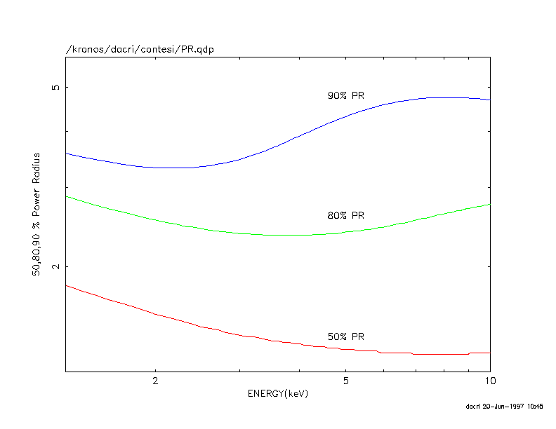
Figure 1 shows the 50 %, 80 % and 90 % power radius as
a function of the energy for the MECS detectors. Extraction regions
of 3-6 arcmin radius are wide enough to collect most photons and
should be used for medium to bright sources (count rate higher than,
roughly, 0.3 counts s![]() ). Extraction radii of 2-3 arcmin can be
safely used for fainter sources. More in detail the most appropriate
value of the extraction radius depens also on the spectral properties
of the sources and, as a rule of the thumb, at similar count rates
larger area should be preferred for softer sources. It is not
recomanded to use extraction radii smaller than 2 arcmin.
). Extraction radii of 2-3 arcmin can be
safely used for fainter sources. More in detail the most appropriate
value of the extraction radius depens also on the spectral properties
of the sources and, as a rule of the thumb, at similar count rates
larger area should be preferred for softer sources. It is not
recomanded to use extraction radii smaller than 2 arcmin.
For the LECS the choice of the extraction radius depends of course on the source brightness but also on the source spectrum below 0.5-1 keV. The LECS PSF gets rapidly very broad toward the lower energies (e.g below the Carbon edge at 0.3 keV) and therefore for very soft sources large extraction regions (i.e. 8 arcmin radius) are recommended. Conversely for absorbed sources, with few photons below 0.5 keV, the same criteria adopted for the MECS can be used.
MECS and LECS event files extracted from the archive or generated
in situ with SAXDAS are not automatically screened for events
for which there is not an attitude solution (i.e. events for which
it is not possible to convert detector coordinates in sky coordinates).
Such events have a ``-1'' in the X and Y columns.
A gti file (GTI_XY.fits) is provided in the SDC archive (in the
archive/${obscode}/event_files directory) to exclude these events.
When extracting LECS and MECS products in sky coordinates it is always needed to screen for these unwanted time intervals. This can easily be done in Xselect loading the GTI_XY.fits file as a filter time file.
Products extracted from the SDC archive are automatically screened for intervals of times with no attitude solution.
When extracting spectra from merged MECS or MECS23 files you need to do the extraction in sky coordinates. The following is an example of Xselect MECS session:
The region file can be generated using SAOIMAGE or just editing a one line .reg file similar to the following:
CIRCLE(252.6,258.2,60.00)
where 252.6 and 258.2 are the sky pixels of the centroid of the source image and 60.00 is the extraction radius in pixels.
LECS spectra can be extracted in RAW, DET or SKY coordinates. We compared the spectra obtained from concentric regions of the same area in the three cases and found no differences. The following is an example of Xselect LECS session:
It is useful for the LECS to know the RAW detector coordinates of the centroid of the source. These can be found direcly by extracting LECS images in RAW coordinates, or converting the DET coordinates in RAW coordinates using the following approximate formulae:
        dx = (DETX-256)*8./14.
        dy = (DETY-256)*8./14.
        RAWX = 131.44 + dx
        RAWY = 124.12 + dy
In Table 2 below the ignore instructions are listed to be used within XSPEC. We strongly recommend the users to use them in performing spectral fits.
The BeppoSAX mirrors suffers for significant vignetting, i.e. reduction of the off axis collecting area due to the shadowing of the inner shells by the outer shells. The vignetting is a steep function of the energy because the inner mirrors are those reflecting the highest energy photons. Therefore the reduction in collecting area is higher at higher energies. Figure 2 shows the vignetting function measured in the MECS as a function of the off-axis angle and energy. Figure 2b illustrates how the vignetting is more important at higher energies as the off-axis angle increases.

The vignetting function has been calibrated using on-ground and in flight data (Cusumano et al. 1998). Effective area files, computed at different off-axis angles, making use of this accurate calibration will soon be available from the SDC anonymous ftp account at www.sdc.asi.it. These are appropriate for point-like sources.
The analysis of sources extended on a scale larger than the
variations of the vignetting function (![]() arcmin)
require the computation of an appropriate effective area file
(Molendi 1998).
This can be done using the SAXDAS program offarea
available in the SAXDAS 2.0 release.
offarea computes a MECS effective are file for a circular
or annular extraction region, given a surface density distribution.
The surface density could be evaluated using for example ROSAT data.
arcmin)
require the computation of an appropriate effective area file
(Molendi 1998).
This can be done using the SAXDAS program offarea
available in the SAXDAS 2.0 release.
offarea computes a MECS effective are file for a circular
or annular extraction region, given a surface density distribution.
The surface density could be evaluated using for example ROSAT data.
The following is the offarea parameter file which gives an idea about how the program should be run.
Name         Opt Type Values  Default    Description
---------------------------------------------------------------------------
surfbrightfile    N   S   any     ""      surface brightness profile file
instrument        Y   S   any     "MECS1" SAX instrument to process
                                            (MECS1/MECS2/MECS3/LECS)
effaonaxfile      N   S   any     "CALDB" on-axis effective area file
effafile          N   S   any     ""      stem of effective area file names
outdir            Y   S   any     "="     directory for output file
psffile           N   S   any     "CALDB" psf parameter file
vignfile          N   S   any     "CALDB" vignetting parameter file
dovign            N   B   yes|no  yes       consider vignetting?
innerrad          Y   R   >0      1.        inner bounding radius (arcmin)
outerrad          Y   R   >0      2.        outer bounding radius (arcmin)
verbosity         Y   I   0-3     2         program verbosity level
help              Y   B   yes|no  no        help flag; if set, display this
surfbrightfile is an ascii file with two columns, the first with the radius in arcsec and the second with the surface brightness profile.
Binning reduces spectral resolution. Usually we bin data because we
want to get Gaussian statistics in our new bins, so to ensure the
applicability of the ![]() test. However, data obeys
the Poisson distribution, so we could use a method of
fitting based on Poisson likelihood. This is actually possible in
XSPEC (using the Cash C estimator) but not very popular. The reason is
that the
test. However, data obeys
the Poisson distribution, so we could use a method of
fitting based on Poisson likelihood. This is actually possible in
XSPEC (using the Cash C estimator) but not very popular. The reason is
that the ![]() distribution is well known and so it is easy to
associate a probability to a
distribution is well known and so it is easy to
associate a probability to a ![]() . On the other hand it is not
possible to easily assess the goodness of a fit or discriminate between
two models using the C statistics.
. On the other hand it is not
possible to easily assess the goodness of a fit or discriminate between
two models using the C statistics.
In case one does not want to struggle with complicate statistic problems, but at the same time one wants to employ the full capability of the instruments, one should make sure that the redistribution matrix is not highly undersampled when binning.
Furthermore, BeppoSAX NFI instruments spectra have a linear canalization
(the width of the electronic channels is constant with energy). Since
the instrument resolution generally scales with the square root of the
energy this means that the lower energies are sampled much less
frequently than the higher energies. Therefore the higher energies
give more contribution to the ![]() (in case of any deviation, real or
systematic).
This means that at low energy a spectral feature is more easily overlooked
than at high energy.
(in case of any deviation, real or
systematic).
This means that at low energy a spectral feature is more easily overlooked
than at high energy.
To avoid these problems one could rebin the spectra with a binning factor which is not constant with energy.
For the LECS and the MECS we generated a number of rebinnig template files to be used in GRPPHA. These files contain a specific rebinning to sample the instrument resolution with the same number of channels at all energies (1, or 2, or 3, or 4, or 5). These files can be found in the SDC anonymous ftp at www.sdc.asi.it.
Background due to high energy particles strongly limits the high energy study of faint extragalactic sources. In these cases particular care should be given to PDS background rejection. Particle background events are rejected through an analysis of their Rise Time signal. At the moment two different stategies are available in SAXDAS for Rise Time based background rejection:
a) fixed Rise Time thresholds
b) Variable Rise Time thresholds, function of the PHA channel of the event and of the temperature of the phoswitchs
The first stategy is the default one. The PDS response matrix has been
calibrated using data reduced in this way. The average, full
band (13-300 keV) PDS residual background is of about 34 counts
s![]() (4 units added together).
(4 units added together).
The second strategy reduces the background by 30-50 % depending on
the energy. It also reduces ``Crab'' like spectra source count rates by
about 7 %. This gives rise to much better signal to noise ratio for
faint sources. The method has been developed and calibrated by the
PDS team at TESRE/CNR using Crab data and does not introduce spectral
systematics for ``Crab like'' spectra sources (power law spectrum with
energy index ![]() ). The method is, however, recommended for
faint sources only i.e. sources for which the uncertainty on the
best-fit slope is higher than 0.1 or so (corresponding to a count rate
smaller than 0.5-1 s
). The method is, however, recommended for
faint sources only i.e. sources for which the uncertainty on the
best-fit slope is higher than 0.1 or so (corresponding to a count rate
smaller than 0.5-1 s![]() . For sources with better statistics,
and intrinsic spectral shape very different from Crab, the use of this
method may introduce a systematic error in the spectral shape.
The method should then be used with care.
In any case the observer should always compare the
spectra extracted with both methods and disregard the one
extracted with the variable Rise Time selection if the spectral shape
is very different from that of Crab and if the two spectra are
statistically inconsistent.
. For sources with better statistics,
and intrinsic spectral shape very different from Crab, the use of this
method may introduce a systematic error in the spectral shape.
The method should then be used with care.
In any case the observer should always compare the
spectra extracted with both methods and disregard the one
extracted with the variable Rise Time selection if the spectral shape
is very different from that of Crab and if the two spectra are
statistically inconsistent.
Spectra obtained from data with the second strategy should be analyzed
with the publicly available matrix. A correction factor should be
applied to the spectral normalization, in addition to the factor that
is in any case needed to take into account the difference in the
absolute flux calibration between the PDS and the other NFI, see
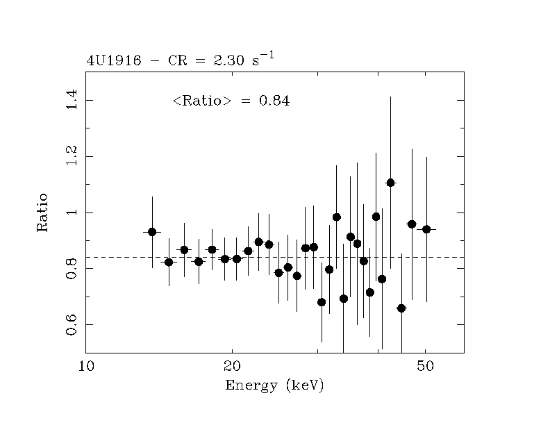
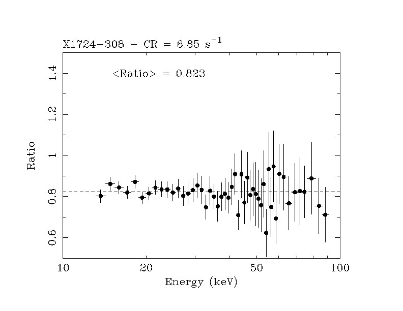
Sect.4.1. In Figure 3 the ratio between spectra reduced with
the two strategies above is shown (variable versus fixed Rise Time
thresholds), for a number of relatively bright sources, with different
spectral shape and count rates in the range 2.3-13 s![]() . The
correction is consistent with being roughly energy independent in all
cases. The average correction factor is of
. The
correction is consistent with being roughly energy independent in all
cases. The average correction factor is of ![]() .
.
Starting from June 1998 the SDC pipelines produce PDS spectra using
both methods. Both spectra are available from the on line
SDC archive from the archive/${obscode}/results directory.
The fixed Rise Time threshold spectrum is called
PDS_01_${obscode}.pha,
the variable Rise Time threshold spectrum is called
PDS_11_${obscode}.pha.

The PDS light curves are well known to exhibit ``spikes'' on timescales
between a fraction of second to a few seconds.
These spikes are due to single particles hits, which
illuminate one crystal and create fluorescence cascades.
The average occurrence rate varies strongly from observation to
observation and can be as high as a few events
per orbit. Typical count rates ranges
between few tens up to several hundreds or even thousands
counts per second.
The spectrum of the spikes is soft. Usually most counts from spikes
are recorded below 30 keV.
The spikes should be removed after the SAXDAS pipeline has been run.
The algorithm to remove them is based on the fact that they appear
in just one of the crystals at any one time:
therefore, inspection of the light curve for each collimator (files
fot_00${fotnumber}_PD_01_[AB].lc)
and removal of all the ``suspicious'' bins.
An automatic script (rmpdssp) will soon be available for this purpose.
 norway>rmpdssp
 =======================================================
 Usage: rmpdssp [F/V] [threshold] [stem]

 Parameters description [in square bracket optional]
 -------------------------------------------------------
 [F/V]        =   Spikes will be removed according to
                  a [F]ixed or a [V]ariable threshold (i.e.
                  each spike which exceeds the mean by
                  5 sigma)
 [threshold] =    if you have chosen a [F]ixed threshold,
                  this is the threshold in sigma.
 [stem] =         string in the PDS product files
                  (e.g.: fot_000295_PD_01_${stem}_A.pha)
 ========================================================
Alternatively, the screening for PDS spikes can be done manually and interactively, using can general FTOOLS like fselect, or within Xselect:
read event PDS_${obscode}_unscreened_qev.evt ./

PDS> set xyname PHWID  PHWID

PDS> set wmapname PHWID  PHWID

PDS> set binsize 2

PDS> extract curve

PDS> plot curve

PDS> filter intensity 2 60
(this is an example, check the lightcurve before
deciding a threshold interval)

PDS> extract events

PDS> save events PDS_${obscode}_qev.evt
The program to extract PDS background subtracted spectra and light curves is pdproducts. The following is the parameter file of this program:
Name         Opt Type Values  Default    Description
---------------------------------------------------------------------------
evfile       N   S    any     ""       equalized event file to process
dirpath      Y   S    any     "./"     directory path for input files
gtidirpath   Y   S    any     "="      directory path for ON/OFF gti files
outdir       Y   S    any     "./"     output path for products
gtifiles     Y   S    any     ""       list of additional gti files,
                                       separated by commas (no blanks)
phalo        Y   R    1-1024  1        Minimum PHA value to consider
phahi        Y   R    1-1024  1024     Maximum PHA value to consider
binlc        Y   R    > 0     2        Size of time bin in light curve (sec)
spectra      Y   B    yes|no  yes      Generate spectra?
lcurves      Y   B    yes|no  yes      Generate light curves?
extonly      Y   B    yes|no  no       Extraction of ON and OFF products only
stem         Y   S    any     "="      root name for products
                                       (no math chars `/'`*'`+'`-')
help         Y   B    yes|no  no       display this
pdproducts is usually run in the following way:
!pdproducts fot_00
![]() fotnumber_PD_01_gti00.fits!
fotnumber_PD_01_gti00.fits!
i.e. by specifying the gti file that should be applied.
This is equivalent to running up to the fifth stage of the PDS SAXPIPE, i.e.: !saxpipe instr=PD entrystage=1 exitstage=5!). Again, it is possible to create scientific products with any set of home-made GTIs (provided they are in FITS format). One has to list them within double quotes, separated by commas without blanks, e.g.:
gtifiles=''fot_00${fotnumber}_PD_01_gti00.fits,mygti.fits,mygti2.fits''.
It is also possible to create light curves in a specific energy band or
with a desired binning size. See above or type pdproducts help=yes
to list all the available options.
The final (background subtracted) spectrum is called
fot_00${fotnumber}_PD_01.pha. Since PDS spectra can have
256, 512, or 1024 channels, in the last two cases an additional
background subtracted spectrum
(fot_00${fotnumber}_PD_01_256.pha) with 256 channels is
produced, to comply with the publicly available PDS response
matrix. If this file is created it should be used in subsequent
analysis.
In addition, on- and off- source spectra and light curves for each of
the two half arrays (e.g.:
fot_00${fotnumber}_PD_01_[AB]ON.pha and
fot_00${fotnumber}_PD_01_[AB]OFF.pha files) are created.
For the PDS we generated a rebinnnig file to be used in grppha which logaritmically rebin the 15-220 keV useful PDS energy range in 18 channels. This file can be found in our anonymous ftp on www.sdc.asi.it.
The program to extract HPGSPC background subtracted spectra and light curves is hpproducts. The following is the parameter file of this program:
Name         Opt Type Values  Default    Description
---------------------------------------------------------------------------
evfile        N   S   any     ""         event list FITS file
indir         Y   S   any     "./"       search path for input file
outdir        Y   S   any     "="        directory for output file
gtidir        Y   S   any     "="        directory for gti files
gtion         Y   S   any     on         tag for collimator ON gti file
gtioffm       Y   S   any     offm       tag for collimator OFF- gti file
gtioffp       Y   S   any     offp       tag for collimator OFF+ gti file
gtivis        Y   S   any     vis        tag for X-ray source visibility gti file
gtiocc        Y   S   any     occ        tag for Earth occultation gti file
gtiagc        Y   S   any     agc  t     tag for the AGC ON gti file
gtifile       Y   S   any     ""         additional gti file
spectra       Y   B   yes|no  yes        Generate background subtracted spectra?
onoffspe      Y   B   yes|no  no         Generate ON/OFF spectra?
photonlist    Y   B   yes|no  no         Generate a cleaned (on source) photon list?
lcurve        Y   B   yes|no  yes        Generate light curves?
eminlc        Y   R   8-20    8          Minimum Energy value for the light curve (keV)
emaxlc        Y   R   8-20    20         Maximum Energy value for the light curve (keV)
binlc         Y   R   >192    192        Binsize of the light curves (sec)
lcminexp      Y   R   0-1     0.2        Light curve minimum exposure fraction
verbosity     Y   I   0-3     2          program verbosity level
help          Y   B   yes|no  no         help flag; if set, display this
hpproducts is usually run in the following way:
hpproducts fot_00${fotnumber}_HP_01_evc.fits
This is in principle equivalent to running the fifth stage of the
HPGSPC Saxpipe (i.e.:
saxpipe instr=HP entrystage=1 exitstage=5). However, it
is preferable to proceed in two separate
steps, performing the pipeline up to the forth stage (default of SAXPIPE) and then running hpproducts, because its current
implementation asks a series
of questions interactively (you may want to answer the default option to
most of them under standard conditions):
[26]crinkley> hpproducts
hpproducts-v2.0.0
o process:[fot_005166_HP_01_evc.fits] fot_005166_HP_01_evc.fits
Directory path for input files:[./]
Output path for products:[=]
additional gti file:[none]
Generate background subtracted spectra?[yes]
Generate ON/OFF spectra?[yes]
Generate light curves?[yes]
Minimum Energy value for the light curve (keV): (8:20.) [8]
Maximum Energy value for the light curve (keV): (8.:20.) [20]
Binsize of the light curves (sec):[192]
Light curve minimum exposure fraction (0.:1.) [0.2]
Generate a cleaned (on source) photon list?[no]
One set of additional GTIs can be specified, providing the name of
a single external GTI file in the above dialog or using the option
gtifiles=mygti.ext in the run string.
The final (background subtracted) spectrum is
fot_00${fotnumber}_HP_01_spt.pha and
the final background subtracted light curve is
fot_00${fotnumber}_HP_01_lc.fits.
In addition, on- and off- source spectra are generated. These are
fot_00${fotnumber}_HP_01_on.pha, fot_00${fotnumber}_HP_01_off-.pha
and
fot_00${fotnumber}_HP_01_off+.pha,
with the last two spectra being the accumulations in each of the two different collimator directions. The background subtracted spectrum is also grouped by the signal-to-noise ratio of each bin and is called
fot_00${fotnumber}_HP_01_spt_grp.pha.
This is the preferred method of binning HPGSPC spectra. For details, type
fhelp hpgroup.
It is also possible to specify the energy range, binning size and
minimum exposure per bin for the light curve
production (see above or type hpproducts help=yes).
To study the BeppoSAX NFI intercalibration we used several observations of the Crab nebula (Crab hereafter) and observations of other bright sources with a reasonably simple spectrum in all four NFI instruments (a power law or a power law with an exponential cutoff). The Crab is observed every six months by BeppoSAX, with the purpose of verifying the instrumental on-flight performance.
We show the results obtained using both SAXDAS 1.1-1.2-1.3, files rev. 1-1.2 (released on December 1996 and September 1997) and SAXDAS 2.0, files rev. 2.0, released on November 1998. We discuss in a following section the differences between the results obtained with the two main revisions.
We use spectra extracted from regions of 8 arcmin for LECS and MECS We test the result on spectra extracted in 4 arcmin regions. We use the ``on axis'' response matrix as provided in the November 1998 release. For the MECS, LECS and PDS these matrices are identical to those in the previous Sept 1997 issue. For the HP the response matrices have been highly improved.
We use PDS spectra extracted using the fixed Rise Time threshold method. We then test the results on spectra extracted using the variable Rise Time threshold method.
Table 3 gives the best-fit results when a simple power-law (absorbed for the imaging instruments) is applied to the spectra of the four NFI separately.
The following points emerge, assuming the MECS as a reference:
The above numbers can be regarded as order-of-magnitude estimate of the systematic uncertainties associated with the spectral shape determination.
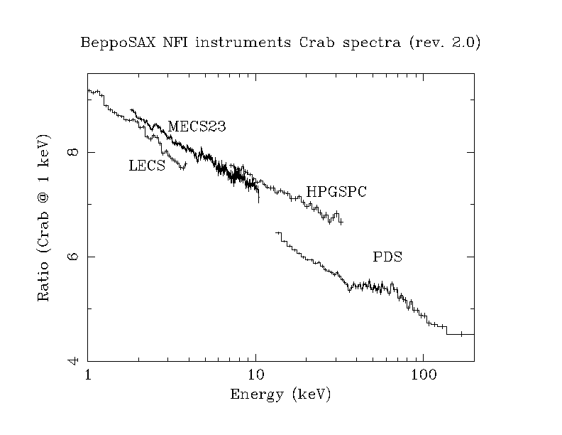
Figure 4 show the four NFI spectra of the Crab
normalized by a simple absorbed (
![]()
![]() ) power-law spectrum with a spectral photon index equal to 2.
Revision 1. and 2. spectra are plotted in Figure 4a)
and b) respectively.
) power-law spectrum with a spectral photon index equal to 2.
Revision 1. and 2. spectra are plotted in Figure 4a)
and b) respectively.
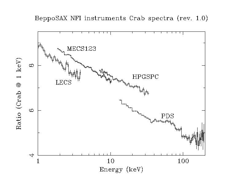
The Crab emission is made up of two distinct components: the pulsar emission and the nebula emission. It is known from phase resolved spectroscopy that the pulsar emission is harder than the nebula emission. The relative contribution of the two components changes consequently with energy, making in principle the total spectrum harder at higher energies. An analysis is ongoing (Cusumano et al. 1999) to disentangle these contributions. It will help also on clarifying the cross-calibration issues on the whole BeppoSAX broadband.
Small differences in the absolute flux determination among the NFI are visible in Figure 4. Because of the large energy range covered, small differences in spectral index can reflect themselves in much bigger differences in the normalization at a certain energy (the value at 1 keV can be directly read from Figure 4 if one extrapolates the spectra at this energy). For this reason we comment on the differences in flux in the energy ranges common to the NFI: 1.8-4.0 keV for the LECS/MECS pair, 7-10.5 keV for the MECS/HPGSPC pair and 13-34 keV for the HPGSPC/PDS pair. One notes that:
![]() [LECS-MECS]
[LECS-MECS]
The LECS spectra have a normalization ![]() 8% lower that that of the
MECS ones during the April 1997 observation and
8% lower that that of the
MECS ones during the April 1997 observation and ![]() 3% lower during the
October 1998. Such variations are to be expected, especially in an extended
source, given the complicated and still not completely calibrated pattern of
obscuration, which is
determined by the mesh of grids which support the LECS entrance
window. The actual value is therefore strongly dependent on the exact
position of the source centroid in raw coordinates. In the above cases
the centroid coordinates are (133.0,127.0) and (131.5,127.5),
for the April 1997 and October 1998 observations, respectively. The new
release of SAXDAS includes a program (lemat), which calculates
the appropriate effective area (*.arf file)
for the exact position of the extraction
region. Alternatively, a set of *.arf pre-calculated files are available
for some standard positions in the SDC anonymous ftp site.
3% lower during the
October 1998. Such variations are to be expected, especially in an extended
source, given the complicated and still not completely calibrated pattern of
obscuration, which is
determined by the mesh of grids which support the LECS entrance
window. The actual value is therefore strongly dependent on the exact
position of the source centroid in raw coordinates. In the above cases
the centroid coordinates are (133.0,127.0) and (131.5,127.5),
for the April 1997 and October 1998 observations, respectively. The new
release of SAXDAS includes a program (lemat), which calculates
the appropriate effective area (*.arf file)
for the exact position of the extraction
region. Alternatively, a set of *.arf pre-calculated files are available
for some standard positions in the SDC anonymous ftp site.
![]() [MECS-HPGSPC]
[MECS-HPGSPC]
the HPGSPC spectra have a normalization ![]() 2% higher than that
of the MECS ones
2% higher than that
of the MECS ones
![]() [PDS-HPGSPC]
[PDS-HPGSPC]
the PDS spectra have a normalization which is ![]() 16-17% lower than
that of the HPGSPC ones
16-17% lower than
that of the HPGSPC ones
The normalization factor between LECS and MECS depends largely on the position of the source in the detector, due to the complex structure of the support of the LECS window. This can be checked finding the source position in DET or RAW coordinates (see Sect.3.1) and using the appropriate LECS matrix. However, residuals systematic uncertainies remains when the source is very close to the wires supporting the LECS window. When fitting simultaneously LECS and MECS data, LECS/MECS normalization ratios between 0.7 and 1 are usually acceptable. Smaller or higher values indicate the model is not appropriate, or that something wrong happened in the data reduction.
We have studied the MECS-PDS flux intercalibration by fitting MECS and PDS spectra of several sources in a wide range of count rate and reasonable simple spectral shapes (a power law or a power law with an exponential cutoff, i.e. spectra with second derivative which does not change sign). Table 4 gives the log of the observations of these sources.
The 2-200 keV MECS and PDS spectra have been simultaneously fitted
with the function
![]() , where C is the model
constant in XSPEC and M(E) is the physical model
(a power-law, with or without an high-energy cutoff).
While the parameters of the model M(E) are
the same for MECS and PDS data, the parameter of the model C is set to
the value 1 when applied to MECS data (i.e. the MECS units are assumed
as the best calibrated instrument) and let free to vary when
applied to PDS data in order to quantify the ratio between
the PDS to MECS normalization.
Table 4
gives the 90 % confidence interval for
, where C is the model
constant in XSPEC and M(E) is the physical model
(a power-law, with or without an high-energy cutoff).
While the parameters of the model M(E) are
the same for MECS and PDS data, the parameter of the model C is set to
the value 1 when applied to MECS data (i.e. the MECS units are assumed
as the best calibrated instrument) and let free to vary when
applied to PDS data in order to quantify the ratio between
the PDS to MECS normalization.
Table 4
gives the 90 % confidence interval for ![]() (the PDS to MECS
normalization). Three of the observations used are part of the
BeppoSAX NFI calibration program (Crab and 3C273), two are public data
(TERZAN 2 and NGC6624, Guainazzi et al 1998, 1999), and four are proprietary
data. The three of the latter sources are indicated with Cal1, Cal2 and Cal3
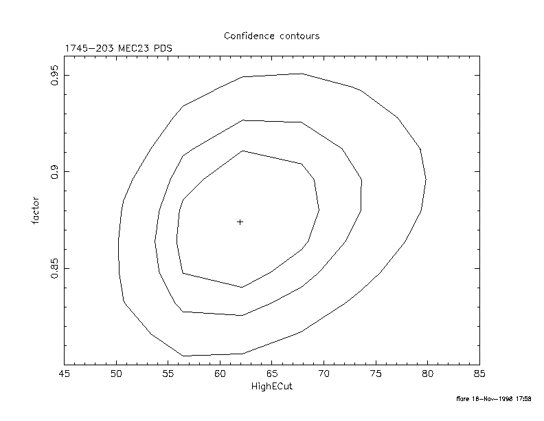
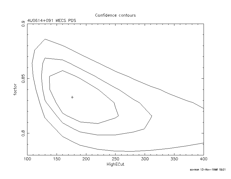
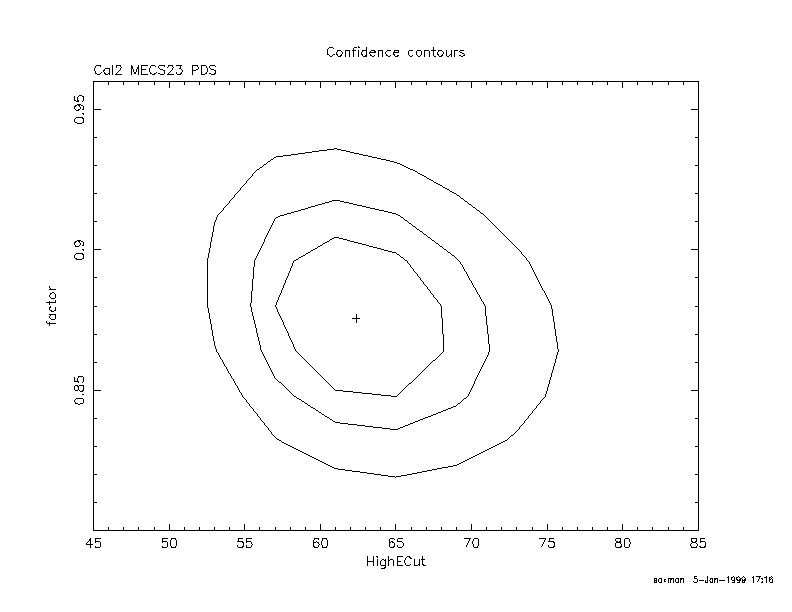
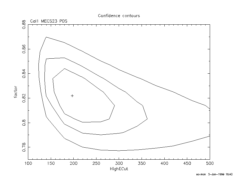
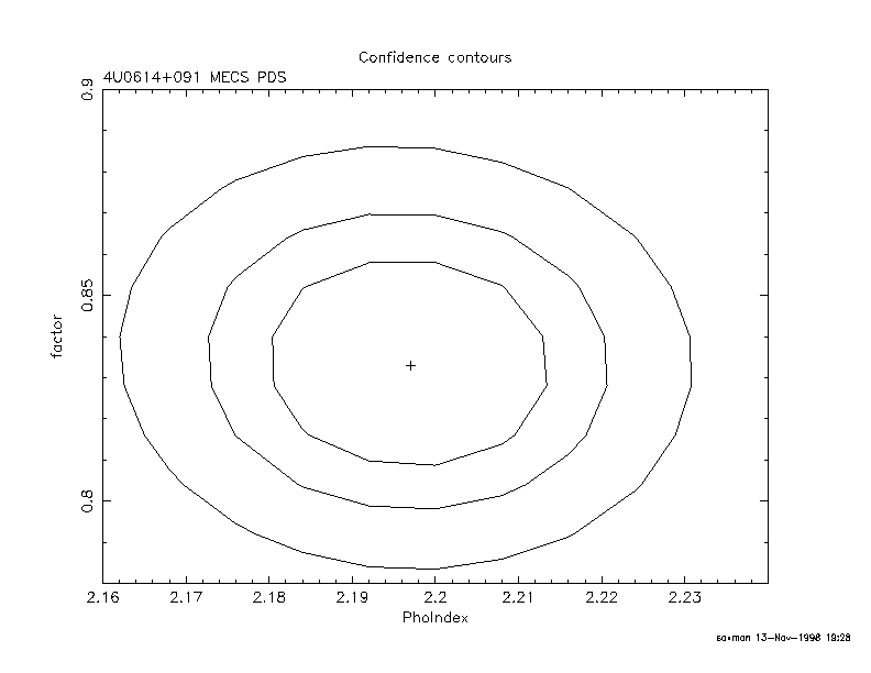
respectively. Figure 5 shows the
(the PDS to MECS
normalization). Three of the observations used are part of the
BeppoSAX NFI calibration program (Crab and 3C273), two are public data
(TERZAN 2 and NGC6624, Guainazzi et al 1998, 1999), and four are proprietary
data. The three of the latter sources are indicated with Cal1, Cal2 and Cal3
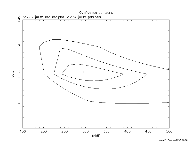
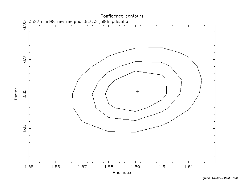
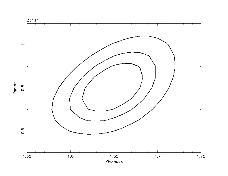
respectively. Figure 5 shows the ![]() contours for this
normalization factor for seven sources. The 90 % confidence
intervals are always in the range 0.77-0.93 but for the faintest
source 3C111, which gives a consistent value for the factor, but the
statistics is not good enough to provide a tight constraint. There is
two cases (NGC6624 and Cal1) a correlation between the PDS/MECS factor
and the cutoff of the spectrum, in the sense that a higher energy
cutoff implies a smaller PDS/MECS factor. The range of variation of
the PDS/MECS factor is however small also in these two cases. We
conclude that at least for bright sources the PDS/MECS factor to be
used in combined MECS-PDS spectral fittings can be safely constrained
between 0.77 and 0.95 (see next section for comments on faint
sources). It is worth remarking that this is a conservative
range. The average and the dispersion of the PDS/MECS
normalization factors of the five sources with more than 2 PDS
counts s
contours for this
normalization factor for seven sources. The 90 % confidence
intervals are always in the range 0.77-0.93 but for the faintest
source 3C111, which gives a consistent value for the factor, but the
statistics is not good enough to provide a tight constraint. There is
two cases (NGC6624 and Cal1) a correlation between the PDS/MECS factor
and the cutoff of the spectrum, in the sense that a higher energy
cutoff implies a smaller PDS/MECS factor. The range of variation of
the PDS/MECS factor is however small also in these two cases. We
conclude that at least for bright sources the PDS/MECS factor to be
used in combined MECS-PDS spectral fittings can be safely constrained
between 0.77 and 0.95 (see next section for comments on faint
sources). It is worth remarking that this is a conservative
range. The average and the dispersion of the PDS/MECS
normalization factors of the five sources with more than 2 PDS
counts s![]() excluduing the Crab
(3C273, TERZAN 2, NGC6624, Cal1 and Cal2) is
0.86
excluduing the Crab
(3C273, TERZAN 2, NGC6624, Cal1 and Cal2) is
0.86![]() 0.03. Note that the PDS/MECS normalization factor
evaluated using the Crab is slightly higher (see Table
4). This difference is probably due to the fact that the Crab
is actually an extended source (on a scale of a 3-5 arcmin) and we
used an effective area file appropriate for an on axis point source.
0.03. Note that the PDS/MECS normalization factor
evaluated using the Crab is slightly higher (see Table
4). This difference is probably due to the fact that the Crab
is actually an extended source (on a scale of a 3-5 arcmin) and we
used an effective area file appropriate for an on axis point source.
Again, all this applies to PDS spectra extracted using the fixed RiseTime thresholds screening. When using the variable RiseTime selection one has to reduce the above factor values by about 7 %.
|
Source confusion ultimately limits the analysis of faint sources in
the PDS and HPGSPC. The FWHM of the collimators of these instruments
is 1.4 and 1.5 degrees respectively, much wider than the MECS and LECS
field of view (28 and 22 arcmin radius respectively). A measure of
the typical systematic error in the PDS count rate is given by
Guainazzi & Matteuzzi (1997) who compared PDS spectra from a number
of `blank fields'. They found a residual count rate of 0.020![]() 0.015
full band.
0.015
full band.
When fitting together NFI spectra of faint sources with count rate not
much higher than the above figure, this limit has to be taken into
account. This can be done in two ways: a) by including in the PDS
spectrum a systematic error of the size of the above residual maximum
count rate (0.035 count s![]() . b) by letting the PDS/MECS
normalization factor to vary in a range given by the figure in the
previous section incremented by the fraction (SC+0.035)/SC, where SC
is the PDS count rate of the source under examination.
. b) by letting the PDS/MECS
normalization factor to vary in a range given by the figure in the
previous section incremented by the fraction (SC+0.035)/SC, where SC
is the PDS count rate of the source under examination.
As described in the previous section, there may be a correlation between the PDS/MECS normalization factor and the power law slope/cutoff energy. When the power law becomes steeper, or the energy cutoff shifts to lower energies, the PDS factor increases.
In the case of a more complex model, i.e. a power law (with/without cutoff) plus a Compton reflection component, the PDS/MECS factor also affects the reflection parameter. If the PEXRAV model included in the XSPEC package is used, the PDS/MECS factor is anticorrelated with the parameter R which roughly represents the solid angle subtended by the cold material reflecting the primary X-ray emission.
The effect of the PDS/MECS calibration uncertainty in the
determination of the amount of reflection is however small. Figure
6 shows the contour plot of the PDS/MECS factor versus the
reflection component in the case of 3C273. Since the 3C273 continuum
is well modeled by a power law with a high energy cutoff and no
reflection component is required by the data, Figure 6
indicates the minimum amount of reflection detectable by a joint
analysis and the MECS and PDS data. A PDS/MECS normalization factor
between 0.7 and 0.95 introduces a spurious reflection not larger than
![]() at 90 % confidence level (and
at 90 % confidence level (and ![]() at 99 %
confidence level).
at 99 %
confidence level).

There is a systematic difference of the order of
![]() , between the LECS Rev. 1 and Rev. 2 spectra, the
latest revision ones being typically steeper (cf. Figure 7)
This implies also a small difference in the best fit normalization
(the best fit normalization of the rev 1.0 spectrum is
lower than that of the rev 2.0 spectrum by about 4 %).
The normalization factor to the MECS is also decreased by the same
amount.
, between the LECS Rev. 1 and Rev. 2 spectra, the
latest revision ones being typically steeper (cf. Figure 7)
This implies also a small difference in the best fit normalization
(the best fit normalization of the rev 1.0 spectrum is
lower than that of the rev 2.0 spectrum by about 4 %).
The normalization factor to the MECS is also decreased by the same
amount.
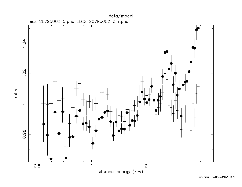
This difference is due to a different Burstlength (a quantity analogous to the RiseTime discussed above for the PDS) selection used in rev 2.0. Events with too short or too long burstlength are rejected (as in all other NFI) to reduce the particle background. As discussed before, for the PDS are available two different strategies (fixes and variable RiseTime selection). For the MECS fixed Burstlength thresholds are used, while for the LECS burstlength thresholds function of the energy are always used. The shape of these thresholds as a function of the energy changed between rev 1. and rev. 2. to correct small systematic residuals at about 0.3-0.4 keV in LECS spectra of bright sources (Orr et al. 1998). The newly adopted burstlength thresholds produce smoother spectra in the 0.1-1 keV range.
The standard background subtration method for the LECS and MECS instrument is the extraction of a background spectrum from a ``blank fields'' event file from a region similar to the ``source'' extraction region in detector coordinates. The reason is that LECS and MECS background strongly varies with the position in the detector (see
http://www.sdc.asi.it/software/cookbook and Chiappetti et al. 1998).
For faint sources accurate background subtraction should be done scaling the ``blank fields'' background at the source position to the mean level of the background around the source during the source observation. Operatively:
We stress that the ``blank fields'' method for background subtraction
usually works reasonably well for high galactic latitudes only
(because the blank fields used are all at ![]() and the background
is obviously higher when looking at the Galactic plane.) For the LECS
this method does not work well for low Galactic latitude sources,
because the background in the Galactic plane has a soft X-ray spectrum
very different from that at high Galactic latitude. The LECS team has
produced a paper in which they discuss this point in much more detail
(Parmar et al. 1999). Briefly, three possible methods to perform
background subtraction of an-axis sources have been tested and
calibrated. The first one makes use of the blank fields event
files, in analogy with the MECS case. The second uses counts obtained
from two semi-annuli near the outside of the LECS field of view to
estimate the background at the source location. The third method uses
ROSAT Position Sensitive Proportional Counter (PSPC) all-sky survey
(RASS) data to estimate the LECS background spectrum for a given
pointing position. The last method will be available for a general
users only when RASS count rate maps are made public. The methods
provide comparably good results, unless for low galactic latitudes
and/or complex region of the sky, where the blank fields tecnique is
no longer adequaate. By comparing the results from these methods, the
relevant systematic uncertainties can be estimated. For high galactic
latitude fields, all 3 methods give 3
and the background
is obviously higher when looking at the Galactic plane.) For the LECS
this method does not work well for low Galactic latitude sources,
because the background in the Galactic plane has a soft X-ray spectrum
very different from that at high Galactic latitude. The LECS team has
produced a paper in which they discuss this point in much more detail
(Parmar et al. 1999). Briefly, three possible methods to perform
background subtraction of an-axis sources have been tested and
calibrated. The first one makes use of the blank fields event
files, in analogy with the MECS case. The second uses counts obtained
from two semi-annuli near the outside of the LECS field of view to
estimate the background at the source location. The third method uses
ROSAT Position Sensitive Proportional Counter (PSPC) all-sky survey
(RASS) data to estimate the LECS background spectrum for a given
pointing position. The last method will be available for a general
users only when RASS count rate maps are made public. The methods
provide comparably good results, unless for low galactic latitudes
and/or complex region of the sky, where the blank fields tecnique is
no longer adequaate. By comparing the results from these methods, the
relevant systematic uncertainties can be estimated. For high galactic
latitude fields, all 3 methods give 3![]() confidence uncertainties
of
confidence uncertainties
of ![]()
![]() count s
count s![]() (0.1-10 keV), or
(0.1-10 keV), or ![]()
![]() count s
count s![]() (0.1-2 keV). These correspond to
0.1-2.0 keV fluxes of 0.7-1.8 and 0.5-
(0.1-2 keV). These correspond to
0.1-2.0 keV fluxes of 0.7-1.8 and 0.5-
![]() erg cm
erg cm![]() s
s![]() for a power-law spectrum with a
photon index of 2 and photoelectric absorption of
for a power-law spectrum with a
photon index of 2 and photoelectric absorption of
![]() and
and
![]() atom cm
atom cm![]() , respectively.
At low galactic latitudes, or in complex regions of the X-ray sky, the
uncertainties are a factor
, respectively.
At low galactic latitudes, or in complex regions of the X-ray sky, the
uncertainties are a factor ![]() 2.5 higher. We refer to Parmar et
al. (1999) for further details on LECS background subtraction.
2.5 higher. We refer to Parmar et
al. (1999) for further details on LECS background subtraction.
To take into account the reduction of the internal background due to
the decay of the MECS calibration sources SDC now distributes two
``blank fields'' files for the MECS instrument, one for the
first year of the mission (time ![]() May 7 1997, MECS_bkg.evt,
total exposure time of 505 ks) and the
second relative to the second year (time
May 7 1997, MECS_bkg.evt,
total exposure time of 505 ks) and the
second relative to the second year (time ![]() May 7 1997
MECS23_bkg.evt, total exposure time of 475 ks).
Observations performed before or after this date
should be background subtracted with the appropriate file.
May 7 1997
MECS23_bkg.evt, total exposure time of 475 ks).
Observations performed before or after this date
should be background subtracted with the appropriate file.
SDC also provides LECS and MECS(2,3) files relative to the internal non-X-ray background, obtained using observations of the ``dark'' Earth. The total exposure time in these files is of 500 ks for the LECS and 1800 ks for the MECS(2,3).
The following tables contain the list of files present in the respective directories of the www.sdc.asi.it anonymous ftp as of December 22 1998:
cd pub/sax/cal/bgd/98_11
LECS_bkg.evt    : The standard LECS background event list for the entire FOV.
LECS_bkg.ps     : A smoothed image of LECS_bkg.evt
LECS_bkg_8.pha  : The LECS 8' radius standard background spectrum evaluated at
                  the standard source position (extracted from LECS_bkg.evt).


LECS_nxb.evt    : The LECS non X-ray background event list for the entire FOV.
LECS_nxb.ps     : A smoothed image of LECS_nxb.evt
LECS_nxb_8.pha  : The LECS 8' radius non X-ray background spectrum evaluated at
                  the standard source position (extracted from LECS_nxb.evt).
LECS_nxb_annuli.pha  : The LECS non X-ray background spectrum of the two
                       semi-annuli close to the edge of the FOV


MECS_bkg.evt.gz : The standard MECS(1+2+3) background event list
                    to be used for observations performed before May 7 1997
MECS_bkg_2.pha  : The MECS(1+2+3) 2' radius standard background spectrum
MECS_bkg_3.pha  : The MECS(1+2+3) 3' radius standard background spectrum
MECS_bkg_4.pha  : The MECS(1+2+3) 4' radius standard background spectrum
MECS_bkg_6.pha  : The MECS(1+2+3) 6' radius standard background spectrum
MECS_bkg_8.pha  : The MECS(1+2+3) 8' radius standard background spectrum
MECS_bkg_10.pha : The MECS(1+2+3) 10' radius standard background spectrum

MECS23_bkg.evt.gz : The standard MECS23(2+3) background event list,
                    to be used for observations performed after May 7 1997
MECS23_bkg_2.pha : The MECS23(2+3) 2' radius standard background spectrum
MECS23_bkg_3.pha : The MECS23(2+3) 3' radius standard background spectrum
MECS23_bkg_4.pha : The MECS23(2+3) 4' radius standard background spectrum
MECS23_bkg_6.pha : The MECS23(2+3) 6' radius standard background spectrum
MECS23_bkg_8.pha : The MECS23(2+3) 8' radius standard background spectrum


MECS2_bkg.evt.gz : The standard MECS2 background event list,
MECS2_bkg_4.pha : The MECS2 4' radius standard background spectrum
MECS2_bkg_6.pha : The MECS2 6' radius standard background spectrum
MECS2_bkg_8.pha : The MECS2 8' radius standard background spectrum

MECS3_bkg.evt.gz : The standard MECS3 background event list,
MECS3_bkg_4.pha : The MECS3 4' radius standard background spectrum
MECS3_bkg_6.pha : The MECS3 6' radius standard background spectrum
MECS3_bkg_8.pha : The MECS3 8' radius standard background spectrum


MECS2_nxb.evt.gz : The MECS2 non X-ray background event list
MECS3_nxb.evt.gz : The MECS3 non X-ray background event list
MECS2_nxb_8.pha  : The MECS2 central 8' radius circle non X-ray background
MECS3_nxb_8.pha  : The MECS3 central 8' radius circle non X-ray background
cd pub/sax/cal/responses/98_11
dir

hpgspc_ott98.arf
hpgspc_sep97.rmf

lecs_130_124_8_sep97.arf
lecs_130_126_8_sep97.arf
lecs_130_128_4_sep97.arf
lecs_130_128_6_sep97.arf
lecs_130_128_8_sep97.arf
lecs_sep97.rmf

mecs1_2_sep97.arf
mecs1_3_sep97.arf
mecs1_4_sep97.arf
mecs1_6_sep97.arf
mecs1_8_sep97.arf
mecs1_sep97.rmf

mecs23_2_sep97.arf
mecs23_3_sep97.arf
mecs23_4_sep97.arf
mecs23_6_sep97.arf
mecs23_8_sep97.arf

mecs2_2_sep97.arf
mecs2_3_sep97.arf
mecs2_4_sep97.arf
mecs2_6_sep97.arf
mecs2_8_sep97.arf
mecs2_sep97.rmf

mecs3_2_sep97.arf
mecs3_3_sep97.arf
mecs3_4_sep97.arf
mecs3_6_sep97.arf
mecs3_8_sep97.arf
mecs3_sep97.rmf

mecs_2_sep97.arf
mecs_3_sep97.arf
mecs_4_sep97.arf
mecs_6_sep97.arf
mecs_8_sep97.arf

pds_256_sep97.rmf

wfc1_iros_dec97.rmf
wfc2_iros_dec97.rmf
cd pub/sax/cal/responses/grouping

lecs_1.grouping
lecs_2.grouping
lecs_3.grouping
lecs_4.grouping
lecs_5.grouping

mecs_1.grouping
mecs_2.grouping
mecs_3.grouping
mecs_4.grouping
mecs_5.grouping

pds_18.grouping
Many people have contributed in developing the SAXDAS
software, running and debugging it, developing and running the data
reduction and data analysis pipelines, developing a strategy for a
careful spectral data analysis and testing it. In particular: Uwe
Lammers, Alessio Matteuzzi, Tim Oosterbrook, Francesca Tamburelli and
Alberto Segreto wrote and tested most of the SAXDAS programs, Paolo
Giommi supervised the project of the SDC on-line archive. Angelo Antonelli,
Angela Malizia and Milvia Capalbi helped in developing and running the
pipelines at the SDC and in populating the SDC data archive.
Luigi Piro, Giancarlo Cusumano and Teresa Mineo contributed to the study
of the NFI intercalibration.
Lorella Angelini tested and verified the data reduction software
and stimulated improvements.
Silvano Molendi, Francesco D'Acri and Alessio Vecchi studied in detail
the MECS PSF and the MECS internal background and provided
support for the generation of the effective area files for extended
sources and background subtraction techniques.
Section 3.2 is indebited to the SSD ``SAXDAS How to Guide'',
version 1.11, mantained by Arvind Parmar.
Giorgio Matt and Cesare Perola verified our data
analysis strategies, discussed them with us and stimulated the writing
up of this manuscript. The four Hardware team (LECS ESTEC team, MECS
IFCAI and IFCTR teams, HPGSPC IFCAI team and PDS TESRE and IAS teams)
took care of instrument calibration and dedicated software
developments.
Boella et al. 1997, A&AS, 122, 327
Conti et al. 1997, proc. SPIE 3113
Chiappetti L. et al. 1998, Nucl. Phys. B (Proc. Supp.), 69/103, 610
Chiappetti L. et al. 1998, Guided Tour to the MECS
http://sax.ifctr.mi.cnr.it/Sax/Mecs
Cusumano G. & Mineo T. 1998, Technical report,
ftp://www.sdc.asi.it/pub/sax/doc/reports/vignetting_rep.ps.gz
Frontera et al. 1997, A&AS, 122, 357
Guainazzi M. et al. 1998, A&A, 339, 802
Guainazzi M., 1999, Proceedings of the 3rd INTEGRAL Workshop
Orr A. et al. 1998, Nucl. Phys. B (Proc. Supp.), 69/103, 496
Manzo et al. 1997, A&AS, 122, 341
Guainazzi, M. & Matteuzzi A. 1998, Technical report,
ftp://www.sdc.asi.it/pub/sax/doc/reports/sdc-tr014.ps.gz
Molendi 1998, Technical report
ftp:/www.sdc.asi.it/pub/sax/doc/reports/arf_extended_sources.ps.gz
Parmar et al. 1997, A&AS, 122, 309
Parmar et al. 1999, A&AS, submitted
This document was generated using the LaTeX2HTML translator Version 99.2beta8 (1.46)
Copyright © 1993, 1994, 1995, 1996,
Nikos Drakos,
Computer Based Learning Unit, University of Leeds.
Copyright © 1997, 1998, 1999,
Ross Moore,
Mathematics Department, Macquarie University, Sydney.
The command line arguments were:
latex2html -t 'SAX Cookbook' -image_type gif -split 3 -show_section_numbers saxabc.tex
The translation was initiated by Michael Arida on 2002-12-17