|
|
Next: Fitting Up: Fitting Previous: Fitting
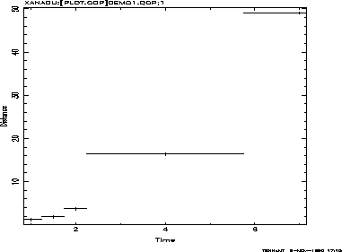
ErrorsThis section describes a QDP file that contains errors and how to control plotting of those errors. The next two sections will describe how to define a model, find the best fitting parameter values, and then estimate the uncertainties on the parameter values. Although the examples will be based on the QDP file containing errors, it is possible (and sometimes better) to fit data without errors. You should now create a DEMO1.QDP file that contains the following: READ Serr 1 2 LAbel X Time LAbel Y Distance 1.0 .25 1.24 .3 1.5 .25 1.86 .3 2.0 .25 3.76 .3 4.0 1.75 16.43 .3 7.0 1.25 49.06 .3The first line in this file is not a PLT command but rather a QDP command. The QDP READ command is used by QDP to tell PLT which vectors contain errors. In this case the READ command tells QDP that vectors 1 and 2 will have symmetric errors; hence, columns 1 and 2 contain data and errors for vector 1, and columns 3 and 4 contain data and errors for vector 2. Following the QDP command are two PLT commands that will be passed to the PLT program and executed before the graph is drawn. Including PLT commands in the QDP file provide a way to override built-in defaults and/or to add labels to the graph. Data lines occur after all the command lines. To read and plot this file, use $ QDP DEMO1 (enter device type) PLT>
The graph that looks like figure 4.1 should now appear.
When you plot data containing errors,
the error attribute is ON,
and the errors plotted.
As described in section 3.3, the line will no longer appear
connecting the data.
If you want to see that line,
then should use PLT> Error OFf PLT> PThis causes the error bars not to be plotted; once again the line connecting the points appears. You should now enter PLT> LIne Step PLT> Pto produce a stepped-line plot. Using Error ON at this time will cause both the stepped line and the errors to be plotted. This is because the LIne Step command sets an internal flag that a line should be plotted and the Error ON command sets another flag to plot errors. The command LIne OFf will turn off the plotting of the (stepped) line. The plotting of a line, errors and markers can all be turned on or off for each vector independently. You should see the LIne, Error and MArker commands, in Appendix B, PLT Command Summary, for more information.
    Next: Fitting Up: Fitting Previous: Fitting
Web Page Maintained by: Dr. Lawrence E. Brown elwin@redshift.gsfc.nasa.gov |


