XMM-Newton Users Handbook


3.7.1.1 Effective area for dispersive spectroscopy

Fig. 116 displays the effective area of both RGS units together (from Fig. 84), compared with different Chandra instrument combinations. In order to avoid overcrowding the figure, the combination of Chandra HRC+LETG is not shown.
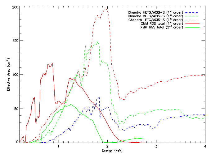
Figure 116: The effective area of both RGS units combined, compared with Chandra's ACIS-S instrument with various transmission gratings. Note that since early after the beginning of the mission, CCD7 in RGS1 and CCD4 in RGS2 are inoperative, thus the effective area in each of the mentioned CCD energy range is reduced by a factor of 2 (see Table 9).
\begin{figure}\begin{center}
\leavevmode
\epsfig{height=0.7\hsize,file=figs/xmm_vs_axaf_specarea.eps}
\end{center}
\end{figure}


European Space Agency - XMM-Newton Science Operations Centre