To a much greater extent than for the GIS, the feasibility of SIS observations is intimately associated with the choice of observing mode. Proposers are strongly encouraged to run PIMMS to determine which modes can be used, especially for bright sources.
There are three limits to how bright a source the SIS can profitably observe:
This limits are detailed below. They can be used in conjunction with the PIMMS simulation program which offers a convenient way of deriving SIS and GIS count rates and of assessing whether a proposed observation falls within these limits. PIMMS is described in the next chapter.
Telemetry is divided into frames, each of which consists of 128 8-bit
words. Under normal operation, SIS event data occupy 1/2 of each
frame (the rest are for housekeeping and GIS data). Since the data
rate is 1, 4, 32 frame s![]() in low, medium, high bit rate,
respectively, the SIS event data can be
acquired and telemetered up to a limit of 64, 256, 2048 word s
in low, medium, high bit rate,
respectively, the SIS event data can be
acquired and telemetered up to a limit of 64, 256, 2048 word s![]() in these three bit rates, to be shared between the two SIS
cameras. One event occupies 16, 4, 2 words in faint, bright, fast
mode, respectively. The combination of CCD mode and bit rate
results in nine possible combinations ranging from 2-512 event
s
in these three bit rates, to be shared between the two SIS
cameras. One event occupies 16, 4, 2 words in faint, bright, fast
mode, respectively. The combination of CCD mode and bit rate
results in nine possible combinations ranging from 2-512 event
s![]() SIS
SIS![]() .
.
Hot and flickering pixel rate has remained roughly constant in 1-CCD mode;
secular increase is, however, observed in 2-CCD mode. The use of an
increased event threshold (![]() 0.4 keV on all chips) has reduced the
number significantly.
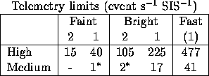
The table below gives the current (early 1997) telemetry limits; updates
will be available through the ASCA GOF web pages, accessible from
0.4 keV on all chips) has reduced the
number significantly.
The table below gives the current (early 1997) telemetry limits; updates
will be available through the ASCA GOF web pages, accessible from
http://heasarc.gsfc.nasa.gov/docs/asca/ascagof.html.

(A ``-'' indicates that telemetry saturation will occur even when source counts are negligible. A `*' indicates that a modest amount of level discrimination is recommended.)
For a quick order-of-magnitude reference for the source counting rate,
use events s![]() SIS
SIS![]() 1 mCrab. However, the simulator
program PIMMS can be used to estimate the SIS count rate more
accurately (see Chapter 10). If you cannot obtain and run PIMMS,
please contact the ASCA GOF at:
1 mCrab. However, the simulator
program PIMMS can be used to estimate the SIS count rate more
accurately (see Chapter 10). If you cannot obtain and run PIMMS,
please contact the ASCA GOF at:
by using our Feedback form and select "ASCA".
In the imaging modes of the SIS (bright or faint), the CCD is exposed
to X-rays for multiples of 4 seconds, depending on the clocking mode
(see Chapter 7 for details). If two photons strike the same or
neighboring pixels during a single exposure, there is no way of
distinguishing this pair of photons from a single photon of a higher
energy (E![]() =E
=E![]() +E
+E![]() ). The count rate must be low enough
that such ``pile-ups'' are kept to an acceptable level.
). The count rate must be low enough
that such ``pile-ups'' are kept to an acceptable level.
The XRT point-spread function (PSF) reduces the number of pile-up
events because photons are spread over many pixels of the CCD.
Nevertheless, for a bright point source, an appreciable amount of
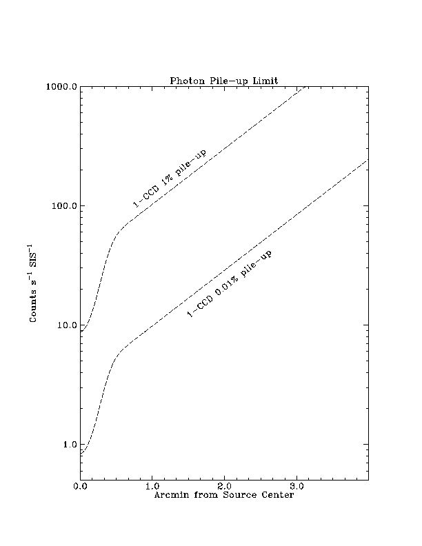
pile-up may occur in the core of the image. Figure 9.2 shows this
effect as a function of the distance away from the center of the
source. A two-component representation of the PSF
(Gaussian plus exponential tail) was used for this calculation; the
probability calculated is that of two or more photons being detected
within a single ![]() pixel area at the position given.
Note that at 0.01 per cent pile-up in this definition, 0.7 per cent of
detected events are caused by multiple photons; the number is 7 per
cent for 1 per cent pile-up.
pixel area at the position given.
Note that at 0.01 per cent pile-up in this definition, 0.7 per cent of
detected events are caused by multiple photons; the number is 7 per
cent for 1 per cent pile-up.
Photon pile-ups do not necessarily invalidate all spectral analysis.
In fact, experimental software exists that can correct the effect
of photon pile-ups, which is likely to be released to the community
in the near future.
However, this software relies on knowing the
correct spectral shape of the source to calculate the correction;
therefore, it can be used only in the regime where the pile-up
correction is small (when it is large, the effect becomes non-linear).
Therefore events detected near the core of the PSF need to be discarded,
reducing the effective count rate by a factor of ![]() typically.
typically.
Figure 9.2 summarizes the photon pile-up limits: use this figure for observations of bright point sources; all lines on this figure are appropriate for 1-CCD mode, as other modes are unlikely. First estimate the total count rate of your source and draw a horizontal line across the figure to estimate the degree to which photon pile-up may affect your data. For example, a 30 cps source may be affected by pile-up at the 1% level within the central 20 arcsec radius of the image, and at the 0.01% level within 2 arcmin. Obviously, you will also need to take into account telemetry saturation limits as described in §9.2.1.
Due to RDD (see Chapter 7 for details), the quality of 4-CCD mode data will have degraded to the point where using 2-CCD mode will always appear to give better results. This will be true for the AO-6 period from the efficiency argument alone; in addition, 4-CCD mode data will have significantly worse energy resolution.
If your science requires the ![]() arcmin
arcmin![]() field of
view, this should be accomplished by using 2-CCD mode, with the two
SIS instruments observing the adjacent
field of
view, this should be accomplished by using 2-CCD mode, with the two
SIS instruments observing the adjacent ![]() arcmin
arcmin![]() areas of the sky. This obviously requires an increased integration
time; if the science depends on the SIS data, then exposure time must
be doubled for reduced coverage. Strictly speaking, to recover the
same amount of photons as would have been acquired immediately
after launch, an additional factor of about 1.1 is necessary as the
efficiency of the 2-CCD mode is becoming lower.
areas of the sky. This obviously requires an increased integration
time; if the science depends on the SIS data, then exposure time must
be doubled for reduced coverage. Strictly speaking, to recover the
same amount of photons as would have been acquired immediately
after launch, an additional factor of about 1.1 is necessary as the
efficiency of the 2-CCD mode is becoming lower.
Proposals requiring this should discuss the scientific need for the wider field of view, now that increased sky coverage requires increased satellite time.
Figures 5.3d & 5.3f show the shape of the XRT point spread function (the CCD itself can be considered a perfect imager by comparison). The shape of the PSF (a sharp core with a broad wing) has two important implications which also apply to GIS observations:
The image scale and area are summarized in Chapter 5 and in Figure 4.5. Important things to note are the small overall field of view of the SIS and the gaps between the CCDs. For an extended source or a cluster of point sources, these features may become problematic. Note further that the use of all four CCDs may not always be feasible if the extended source is bright (see telemetry limit above). If an extended source requires all four CCDs yet is too bright for the 4-CCD mode, one can in principle use 2-CCD mode and use complementary chips so that SIS-0 covers one half of the field and SIS-1 the other. However, this would be considered a non-standard request.
The clocking mode determines the time resolution of the
observations to a multiple of 4 seconds (i.e.,there is no information
whatsoever on when, during those ![]() seconds, a particular
photon was detected).
seconds, a particular
photon was detected).
Fast mode works by continuously reading out one of the four CCDs. The highest possible time resolution is 15.625 msec, with the following caveats.
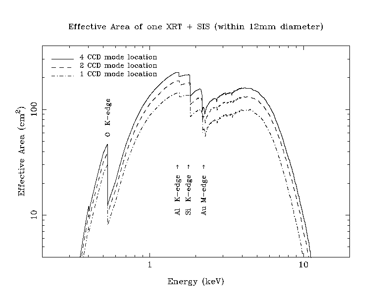
The combined effective area of 1 XRT+SIS (including thermal shield
and the blocking filter) is plotted in Figure 9.5. The combined
throughput for XRT+SIS is measured on-board by cross calibrating
from XRT+GIS, which is in turn calibrated using observations of
the Crab (which is too bright for the SIS). The XRT+SIS calibration
is limited by (1) the accuracy with which the Crab spectrum is known;
(2) accuracy with which the energy dependent point-spread function of
the XRT has been estimated; (3) the counting statistics in the GIS/SIS
cross-calibration observations; and (4) below ![]() 0.7 keV, the need
to extrapolate the spectrum of cross-calibration target from the GIS
range.
0.7 keV, the need
to extrapolate the spectrum of cross-calibration target from the GIS
range.
Up to date information on the limitation of SIS effective area (and other) calibration can be found on the ASCA GOF home page.
Spectral resolution of SIS, in the absence of photon pile-ups, is determined by the Fano factor, thermal noise (fluctuation in the number of electrons), and the read-out-noise (RON). Thermal noise is reduced by cooling the CCD. As a result, the best-case FWHM resolution at photon energy E (keV) is:
![]()
At launch, RON was about 5 e![]() RMS and the Fano factor was
RMS and the Fano factor was
![]() 0.12. The effect of non-uniform CTI has been modeled by
the SIS team as a linear increase in the effective Fano factor:
0.12. The effect of non-uniform CTI has been modeled by
the SIS team as a linear increase in the effective Fano factor:
![]()
Where t is time since launch in seconds, and ![]() is 2.7
is 2.7![]() for SIS-0 and 3.3
for SIS-0 and 3.3![]() for SIS-1. The effective RON has
become somewhat worse than 5 e
for SIS-1. The effective RON has
become somewhat worse than 5 e![]() RMS in 2-CCD mode due to RDD effects
(and much worse in 4-CCD mode). The resolution of SIS-1 without RDD,
according
to the above formulae, at 6 different epochs, are plotted in Figure 8.5b.
RMS in 2-CCD mode due to RDD effects
(and much worse in 4-CCD mode). The resolution of SIS-1 without RDD,
according
to the above formulae, at 6 different epochs, are plotted in Figure 8.5b.
Note, however, the above formula applies only to single-pixel events. For split events, where the electrons produced by the photon are spread over several pixels, all the PHA values from those will normally be added together to maximize the chance of recovering the true photon energy. This, however, effectively multiplies the RON.

Figure 9.2: The extent to which bright source data may be affected by photon pile-up as a function of count rate and off-axis angle. See text for details.

Figure 9.5: The effective area of a single SIS and XRT combined for three off-axis angles (0, 5, 10 arcmin).