| About ROSAT |
ROSAT Home Page | ROSAT Images |
|---|
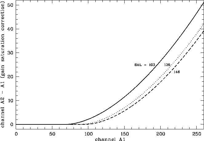
At large charge input (high energy photons as well as high count rate) some saturation of the gain is arising in the PSPC. The fall-off in the signal amplification as a function of event amplitude has been modeled using spectral calibration data (cf. Eq. (F.6)) . At present the rate gain effect is not taken into account.
The offset values ![]() for
for ![]() 135, 146, and 103
are
135, 146, and 103
are ![]() 89.2, 96.1, and 69.1, respectively.
Below these values thresholds gain saturation is negligible.
89.2, 96.1, and 69.1, respectively.
Below these values thresholds gain saturation is negligible.
According to
Chap. 3
the rate gain effect can be understood in terms of pseudo-continuous
presence of a substantial electron cloud causing a reduction in the
electronic field.
Measurements at the PANTER test facility have shown a drop of
the gain of 1% at E = 1.487keV and 2% at E = 3keV for an
X-ray count rate of 500s ![]() .
Further investigations were planned.
.
Further investigations were planned.
Figure F.3 shows the PHA channel difference between the non-linearity and gain saturation correction.

Figure F.3: Difference between the channels after gain saturation correction
( ![]() ) and after non-linearity correction (
) and after non-linearity correction ( ![]() ) as function of
) as function of
![]() according to Eq. (F.6).
The correction effect is shown for three typical gain values
(
according to Eq. (F.6).
The correction effect is shown for three typical gain values
( ![]() , 135, 146).
, 135, 146).
Parameters:
SASS source code: package PSPC, bubble CT, subroutine CGS
SASS files: none

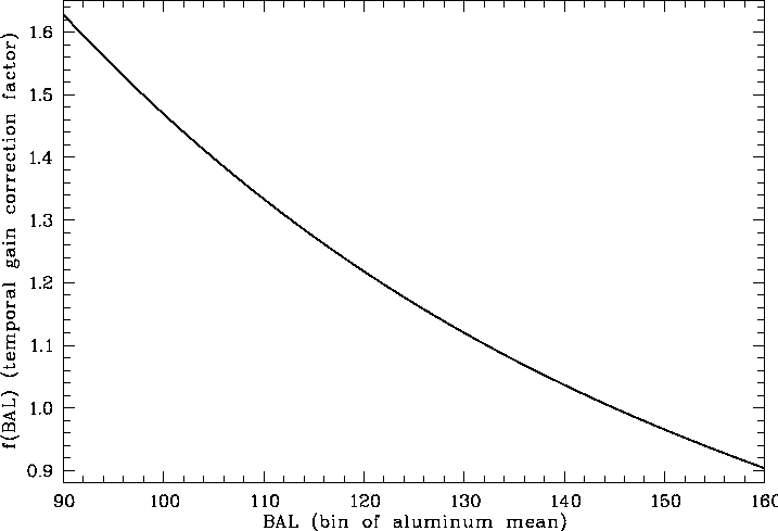
Figure F.4: The temporal gain correction factor ![]() according to Eq.(F.7)
as function of the gain (expressed in terms of the
Al K
according to Eq.(F.7)
as function of the gain (expressed in terms of the
Al K ![]() line bin
line bin ![]() ).
It is
).
It is ![]() ,
,
![]() ,
and
,
and ![]() .
.