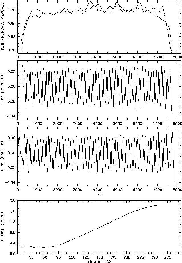
Figure F.8: Spatial gain correction terms according to Eq.(F.12). Top panel:
| About ROSAT |
ROSAT Home Page | ROSAT Images |
|---|

Figure F.8: Spatial gain correction terms according to
Eq.(F.12).
Top panel: ![]() for PSPC-C (solid)
and PSPC-B (dashed). Middle panels:
for PSPC-C (solid)
and PSPC-B (dashed). Middle panels: ![]() for
PSPC-C (upper) and PSPC-B (lower).
Bottom panel:
for
PSPC-C (upper) and PSPC-B (lower).
Bottom panel: ![]() (equal for both PSPCs).
(equal for both PSPCs).

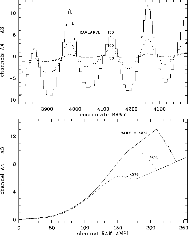
Figure F.9: Effect of the spatial gain correction (SGC) in low-gain mode
![]() for PSPC-B.
Top: SGC as a function of the measured
y-coordinate (
for PSPC-B.
Top: SGC as a function of the measured
y-coordinate ( ![]() , perpendicular to the anode wire direction)
for 3 values of the measured pulse-height:
, perpendicular to the anode wire direction)
for 3 values of the measured pulse-height: ![]() (solid), 100 (dotted), and 50 (dashed).
Bottom: SGC as a function of the measured
pulse-height
(solid), 100 (dotted), and 50 (dashed).
Bottom: SGC as a function of the measured
pulse-height ![]() for three different measured positions:
for three different measured positions:
![]() (solid), 4275 (dotted), and 4276 (dashed).
SGC does not depend on
(solid), 4275 (dotted), and 4276 (dashed).
SGC does not depend on ![]() (parallel to anode wire direction).
(parallel to anode wire direction).
![]() ,
, ![]() , and
, and ![]() correspond in the figure to
RAW_AMPL RAWX and RAWY, respectively.
correspond in the figure to
RAW_AMPL RAWX and RAWY, respectively.

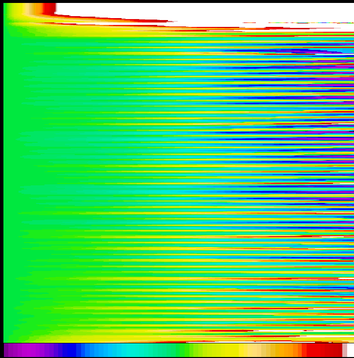
Figure F.10: Spatial gain correction effect ![]() as a function of PSPC-B position (
as a function of PSPC-B position ( ![]() , top to bottom) and
raw amplitude (
, top to bottom) and
raw amplitude ( ![]() , left to right) for
, left to right) for
![]() ;
the color bar ranges from -22 to +22 channels.
;
the color bar ranges from -22 to +22 channels.

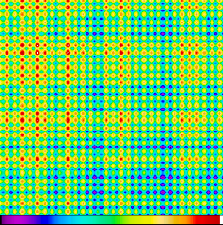
Figure F.11: Spatial gain correction: effect of interchange of x and y axis
as a function of PSPC-B position (detector coordinates
![]() and
and ![]() ,
i.e., the central quarter of the PSPC):
again
,
i.e., the central quarter of the PSPC):
again ![]() and
and ![]() have been used,
the color bar ranges from -10 to +10 channels.
The small-scale inhomogeneities reflect the anode wire spacing.
have been used,
the color bar ranges from -10 to +10 channels.
The small-scale inhomogeneities reflect the anode wire spacing.
Besides the temporal gain variations
(cf. Sect. F.4)
spatial variations in the gain of the PSPC effect the measured
pulse-height.
Mechanical inaccuracies of the grid system lead to different
electric field strengths and hence different gains.
Additionally, the anode wire grid causes a ``binning'' with the period
of the anode wire distance (1mm, about ![]() detector pixels).
During pre-flight ground calibrations using slit masks instead of the
PSPC entrance window spatial gain variations have been determined.
Significant effects have been found perpendicular
to the anode wire direction (i.e., in y-direction) while parallel
to the anodes the effect was negligible (
detector pixels).
During pre-flight ground calibrations using slit masks instead of the
PSPC entrance window spatial gain variations have been determined.
Significant effects have been found perpendicular
to the anode wire direction (i.e., in y-direction) while parallel
to the anodes the effect was negligible ( ![]() ).
The effect also depends on the depth within the counter
where the photon is absorbed (and therefore on the photon energy).
).
The effect also depends on the depth within the counter
where the photon is absorbed (and therefore on the photon energy).
In SASS the pulse height ![]() is obtained depending on the
electronic position corrected coordinate
is obtained depending on the
electronic position corrected coordinate ![]() according to
Eq. (F.12).
The energy-dependent term
according to
Eq. (F.12).
The energy-dependent term ![]() has been determined at the
Al K
has been determined at the
Al K ![]() line energy and should thus be normalized to unity
at channel 151; it is shown in
Fig. F.8 (bottom).
The spatial corrections are expressed in a low-frequency term
line energy and should thus be normalized to unity
at channel 151; it is shown in
Fig. F.8 (bottom).
The spatial corrections are expressed in a low-frequency term
![]() (see Fig. F.8, top)
and a high-frequency term
(see Fig. F.8, top)
and a high-frequency term ![]() (see Fig. F.8, middle)
which reflects the anode wire spacing.
In practice SASS uses
(see Fig. F.8, middle)
which reflects the anode wire spacing.
In practice SASS uses ![]() (nearest integer of
(nearest integer of ![]() );
if
);
if ![]() then the value for
then the value for ![]() is taken.
The spatial correction tables
is taken.
The spatial correction tables ![]() used by SASS have 800 elements with
used by SASS have 800 elements with ![]() ;
for
;
for ![]() the corresponding value for
the corresponding value for ![]() is used.
This has no effect as the table values for
is used.
This has no effect as the table values for
![]() (PSPC-B) and
(PSPC-B) and ![]() (PSPC-C) are constant anyway.
(PSPC-C) are constant anyway.
Figure F.9
illustrates the effect of the spatial gain correction
close to the detector center ( ![]() , PSPC-B)
in low-gain mode (
, PSPC-B)
in low-gain mode ( ![]() ).
The top panel contains the relation of the effect with coordinate
).
The top panel contains the relation of the effect with coordinate
![]() (for 3 values of the measured pulse-height).
The bottom panel shows how strong the effect depends on the position
which results from the use of the roughly binned correction tables
and introduces spectral artifacts.
Figure F.10 gives the spatial gain correction
(for 3 values of the measured pulse-height).
The bottom panel shows how strong the effect depends on the position
which results from the use of the roughly binned correction tables
and introduces spectral artifacts.
Figure F.10 gives the spatial gain correction
![]() as a function of amplitude
as a function of amplitude ![]() (from left to right, 1 to 256)
and position
(from left to right, 1 to 256)
and position ![]() (from top to bottom, 1 to 8192).
Obviously, the effect becomes more important for higher channels.
The color bar ranges from -22 to +22.
(from top to bottom, 1 to 8192).
Obviously, the effect becomes more important for higher channels.
The color bar ranges from -22 to +22.
Another inconsistency is of a more severe nature.
[Hasinger and
Snowden1990] as well as
Chap. 3 (PSPC) and
Chap. 8 (SASS)
use the x-coordinate as input in the correction formula
Eq. (F.12)
instead of the y-coordinate
[Turner et al.1995].
This means, that no correction had been applied by SASS perpendicular
to the anode wires as required but parallel to the anode wire direction.
For positions ![]() this error vanishes.
However, as the on-axis position is not in the detector center,
(4119|3929) instead of (4096|4096), the target positions are
significantly offset from this line and the improper applied correction
has a net effect.
On the other hand, this effect is reduced due to the wobble motion
(
this error vanishes.
However, as the on-axis position is not in the detector center,
(4119|3929) instead of (4096|4096), the target positions are
significantly offset from this line and the improper applied correction
has a net effect.
On the other hand, this effect is reduced due to the wobble motion
( ![]() , equivalent to
, equivalent to ![]() detector pixels in x
as well as in y direction) as the source position
(relative to the detector) moves by more than the anode wire spacing.
The wobble is performed parallel to x = y there is still a major
effect on the amplitudes.
This error has recently been corrected in SASS.
The REV2 survey data as well as pointed data processed with SASS
release 7.2 (or later) have the correct SGC applied.
Figure F.11
gives the spatial gain correction
detector pixels in x
as well as in y direction) as the source position
(relative to the detector) moves by more than the anode wire spacing.
The wobble is performed parallel to x = y there is still a major
effect on the amplitudes.
This error has recently been corrected in SASS.
The REV2 survey data as well as pointed data processed with SASS
release 7.2 (or later) have the correct SGC applied.
Figure F.11
gives the spatial gain correction
![]() if the x and y axis are interchanged in the
correction procedure (SASS versions 7.1 and lower) as a function
of detector position (
if the x and y axis are interchanged in the
correction procedure (SASS versions 7.1 and lower) as a function
of detector position ( ![]() from left to right
and
from left to right
and ![]() from top to bottom).
The color bar ranges here from -10 to +10.
from top to bottom).
The color bar ranges here from -10 to +10.
After the spatial gain correction the amplitude ![]() should not depend
on where the photon has been detected in the PSPC.
Finally, the value
should not depend
on where the photon has been detected in the PSPC.
Finally, the value ![]() is written into
the photon event table (pulse-height invariant channel PI).
is written into
the photon event table (pulse-height invariant channel PI).
Parameters:
SASS source code: package PSPC, bubble CT, subroutine DCORG
SASS files: